32 digital I/O, TTL compatible (16 in and out)
+/- 5 volt A/D input range (software programmable gain)
25 kHz maximum A/D sample rate.
One D/A output either 0-5 or 0-10 v.
included some basic software drivers.
Computer Control outline…
This section will evolve as I build this thing.
Last updated:January 14, 1998
This is more of an outline for me to keep track of what’s up with the project and where I’m at. Its also a big notepad of all the facts in case I need to look something up. I don’t know if this is helpful to anyone out there in cyberspace but I know its going to be ugly until I get the thing running.
For computer control of the brewery, I looked around for a decently priced system that would have the A/D lines I needed for the temperature stuff and digital I/O for control. I looked at several options and finally went with a PC card solution. I went with this kind of approach because I have a lot of old computers around the shop I could use to run the brewery and not be out any money. If you didn’t want have a stand alone integrated computer for you brewery, you might not want to go this route.
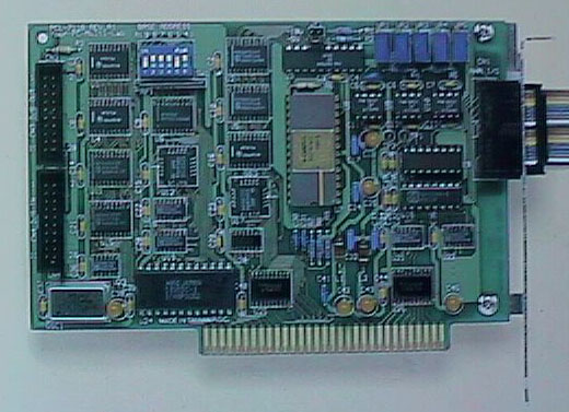
The board I picked was a Advantech PCL 711S. I paid $299 from Jameco and picked it up locally since I made up my mind in the middle of the UPS strike. Its a 8 bit card that has the following stats:
|
8 A/D inputs with 12-bit
resolution 32 digital I/O, TTL compatible (16 in and out) +/- 5 volt A/D input range (software programmable gain) 25 kHz maximum A/D sample rate. One D/A output either 0-5 or 0-10 v. included some basic software drivers. |
For the A/D input, this was perfect for the temperature probes (see LM35 below). I could get 12 bit resolution or close to it because you could program the gain to 0-1.25 v and read right from the sensors without losing too much. The modules can even be adjusted.
In order to make the brewery truly computer controlled, I was going to have to have the heating elements controlled by the board somehow also. The idea of using gas with ignitors seemed difficult so I decided to use electric elements. I just needed a way to control how hot they were so that it wouldn’t boil over and I could maintain temperature when I needed to.
My original idea to control the heating elements was to use the basic design of a lamp dimmer. I had done some research on the Usenet archive on Dejanews and found a gentleman, Ron LaBorde, who had used a dimmer in this fashion control his brewery heating elements. Using his schematic and a dimmer control that could be controlled by a DC voltage, I thought I had it figured out.
It wasn’t until I had bought the dimmer module that another solution came to me. Why not control the heating element directly by turning the power on and off so many times a second? I decided to use Solid State relays to do the job. These relays can be controlled by a DC voltage of 3-32 volts so I could run it directly from the ttl output. I would just control it with software this way.
Before I decided to build this thing, I first wanted to make sure this things wasn’t going to cost a fortune to operate. I made some post to the net and got a response from Ken Schwartz about his 5 gallon electrically heated brewery. I was able to calculate how long it would take to heat things up using formulas on his web page. From this number I could also figure out the cost based on what the utilties cost in my area. Everything seemed reasonable at about $5 dollars per 15 gallon batch on the outside.
Analog/Digital Input (8 total)
| label | description |
| T1 | Hot Liquor Tank temp. |
| T2 | Mash Tun grain temp. |
| T3 | Mash Tun bottom temp |
| T4 | Mash recirc temp |
| T5 | Sparge Temp |
| T6 | Boil Kettle temp. |
| T7 | Final Wort (after chiller) temp. |
| T8 | HLT level indicator (ala stone brewing?) |
The temperature control is all based on using the LM35CZ (so called "Precision temperature sensor") described by Ken Schwartz. These IC give 10 mV/ degree Celsius. The LCD module on the other hand can only read from 0-200 mV. I had originally designed the circuit described by Ken Schwartz to run LCD modules on my console but kept having problems adjusting the low and high set pots. After numerous trials, I finally decided to try and easier solution. I replaced the circuit with a simple op amp design that divides the voltage by 10 without worrying about adjusting the low point. For the computer control, I can calibrate the temperature with software (which I do for a living) and fix any problems. The control panel can just read me what the sensors sees. And besides, the sensors are pretty accurate in any case.
Digital Output Lines (16 total)
| label | description | type | notes |
| O1 | Recirculation Pump | RELAY | L,M3 green |
| O2 | Sparge Water Pump | RELAY | L,M3 green |
| O3 | Hot Liquor Tank Heater | RELAY, SSR40 | L, M2 red |
| O4 | Mash recirculation Heater | RELAY, SSR40 | L, M2 red |
| O5 | Boil Kettle Heater | RELAY, SSR40 | L, M2 red |
| O6 | Mill Motor | RELAY | L,M3 |
| O7 | Boil Kettle stirrer | RELAY | L,M3 |
| O8 | Boil Kettle Fan | RELAY | M3 |
| O9 | Hop Solenoid 1 | RELAY/SOLENOID | |
| O10 | Hop Solenoid 2 | RELAY/SOLENOID | |
| O11 | Hot Liquor Tank Water inlet valve | RELAY/2way PVC VALVE | M1 |
| O12 | Chiller Water inlet Valve | RELAY/2way PVC VALVE | M1 |
| O13 | Mash Tun Outlet Valve | RELAY/2way SS VALVE (1/4") | L,M |
| O14 | Mash Tun Recirc Valve | RELAY/2way brass | L,M |
| O15 | Mash Tun Recirc Hot water valve/Sparge Hot Water valve | RELAY/2way brass RELAY/2way brass |
L,M |
| O16 | Nitrogen purge of Recirc | Relay/2way | L,M |
note: L - lamp indicator on control panel, M - manual overide control
The SSR40 are Solid state relays with zero cross detection circuitry built in rated to 40 Amps. This relay is controlled by 3-32 volts dc and only turns on when the AC line goes to zero during the cycle. This reduces the surge normally experienced with random fire relays and should reduce the R interference. These relay were mounted onto heat sinks with screws and heat sink compound and mounted to the side of the computer case. Click here to see the relays with heat sinks.
The relays are a kit from Velleman labelled the K6714 Universal Relay card. This relay card allows TTL input to control up to 220v ac with 5A current. The relay card only comes with enough parts for 8 realys but can be expanded to 16. It also has parts you can add for boosting TTL signals to power the circuit, noise reduction circuitry, manual switches and LED indicators. All these were bought from Jameco to pretty much double the cost of the board. To see a picutre of the finished board click here.
The hot liquor tank inlet and the chiller water inlet are only normal room temperature water valves. To save money, Im going to use brass valves with stainless internal pats from Grainger. Originall I was going to use parts from Cole Parmer part number FK-98501-20 for $79 a piece. After examining Zymico's site on his own experiences with valves and checking Graingers specs, these valves look better.
| Valve | # | NPT (F) | Orifice size | part number Grainger | cost | Extension |
| Mash Tun Recirc
Hot water valve/Sparge Hot Water valve Nitrogen purge of Recirc |
3 | 1/2" | 5/8" | 1A577, 3A440 | 57.90 + 16.33 | 232.78 |
PVC valves from HSC surplus.
| Valve | # | NPT (F) | Orifice size | cost | Extension | |
| HLT water inlet Chiller water inlet. |
2 | 5/8" | 5/8" | 1A577, 3A440 | $7.00 | 14.00 |
Digital Input Lines (16 total)
In the beginning, Im not going to worry about getting these sensors connected. Instead, Im going to use sensor lights on the control panel to monitor the controls directly.
| label | description | type |
| I1 | Hop container 1 sensor | switch |
| I2 | Hop container 2 sensor | switch |
| I3 | Flow meter Mash tun | flow meter |
| I4 | Pump Sparge on M/O | panel switch setting |
| I5 | Pump Sparge on A | panel switch setting |
| I6 | Pump Recirc on M/O | panel switch setting |
| I7 | Pump Recirc on A | panel switch setting |
| I8 | Fan on M/O | panel switch setting |
| I9 | Fan on A | panel switch setting |
| I10 | HLT tank overflow | float switch |
| I11 | ||
| I12 | Boil Stirrer on M/O | panel switch setting |
| I13 | Boil Stirrer on A | panel switch setting |
| I14 | Heater HLT On/Off | Relay V indicator |
| I15 | Heater Mash On/Off | Relay V indicator |
| I16 | Heater Boil On/Off | Relay V indicator |
The liquid level switches may come from Cole Parmer. The switch are just little switches at the door opening to see if its open or closed and the flow meter is probably a Cole Parmer thing.
Switch inputs I4-I13 represent the settings of the toggles on the panel. M/O represents the switch set to Manual Overide ON whereas A represents setting to Automatic control by the computer. Neither set means its in the Manual override Off position.
I14-I16: these represent the state of the Heater relay actuator regardless of the switch setting of Manual or Automatic.
Suppliers:
| Jameco 1355 Shoreway Road Belmont, CA 94002-4100 (415)592-8097 |
Cole-Parmer 625 East Bunker Court Vernon Hills, IL 60061 800-363-7400 |
Grainger All over the US call for local dealer 800-323-0620 |
| Overview | The Mash Tun | Brewery stand | Hot Liquor Tank | Boil Kettle, Hopback and Cooling |
| Control Panel | Computer Control and data acquisition | Grain Mill | Draught Beer Cooler | HOME |